How Do Circuit Boards Work
What is a circuit board and how does it work?
A circuit board is a flat piece of material that holds and connects electronic components using conductive pathways. It works by providing a platform for the components to be mounted and interconnected, allowing electrical signals to flow between them and enabling the functioning of electronic devices.
Technology is one of humankind’s most profound inventions transforming our existence in every aspect of our life. History is great evidence of this fact. From the start of the ‘Old Stone Age’ to today’s ‘Modern Age,’ we have come a long way. ‘Evolution of Technology‘ is the journey of our social and cultural growth since the discovery of fire and has been a significant catalyst in shaping how we live, act and think. There were many stages in our technological evolution, which have thus far led us to our present state of comfort and convenience.
But going down the rope of history, this comfortable lifestyle may not have been possible without circuit boards. Meaning, without circuit boards our lives, our world would have been very different. From communications to entertainment technology, from defense to transport to health, education, and every area of our life, circuit boards have played a vital role in modern life. These small boards are not only at the heart of every electronic device, but they have played a dynamic role in every industry that relies on technology or is defined by technology.
What is a Circuit Board?
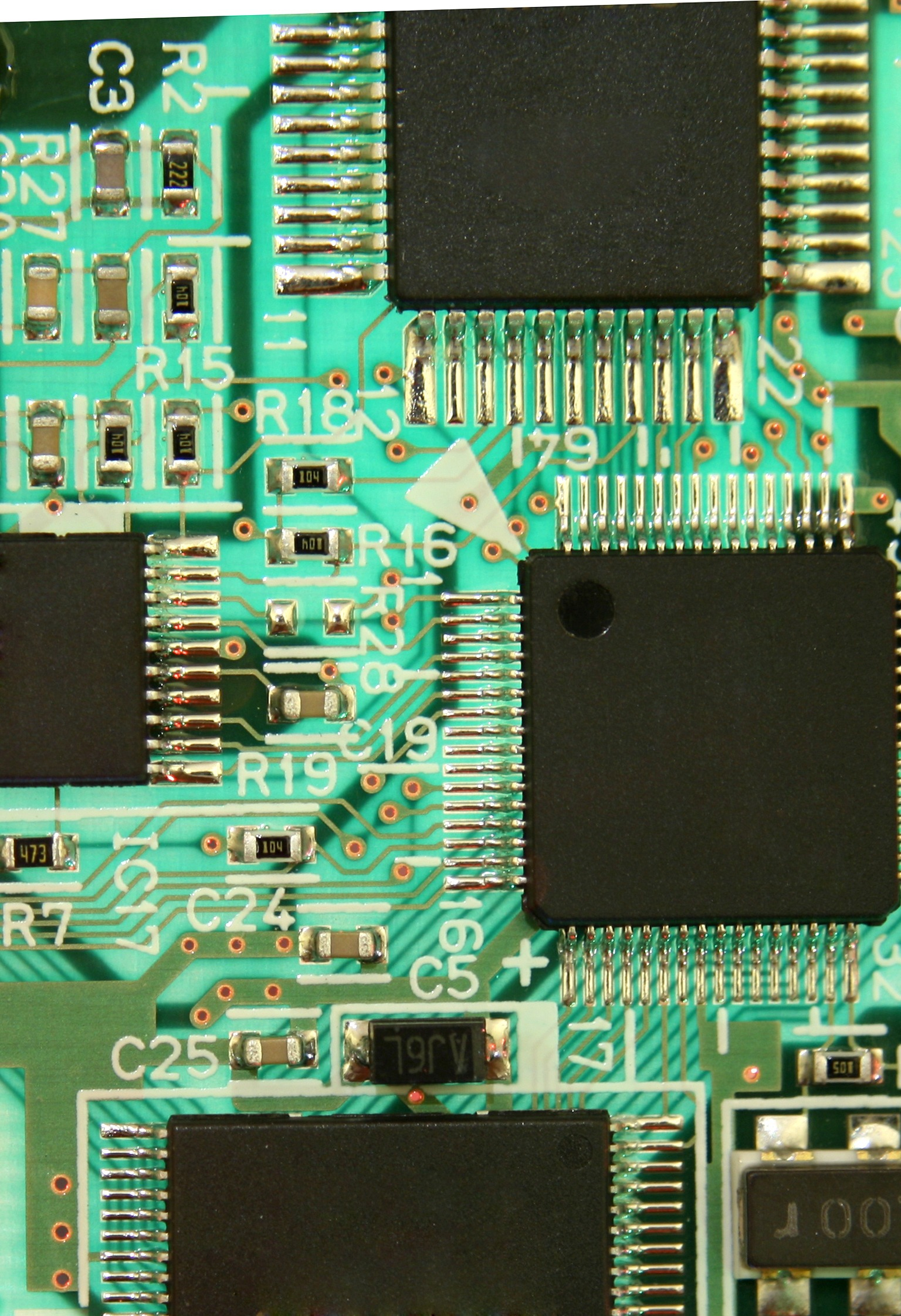
Simply speaking, a circuit board is a printed board that has electrically conductive pathways called ‘traces’ that connects electronic components to each other. Circuit boards are one of the most important inventions that heralded the onset of electronic technology. With the evolution of technology, the complexity of these boards has also evolved, but the underlying concept remains the same.
Circuit boards, as we know them today, result from many inventions, discoveries, and improvements that marked the course of modern technology.
Simplify the Process
Circuit boards greatly simplify the electrical wiring process by replacing many components that once had to be wired through solder or cable with simpler and easier to assemble printed circuit boards. Circuit boards are made of many electrical components and have become complex and sophisticated, sometimes with as many as 30 or more layers. Layers of the circuit board are linked together by traces, with some layers being specialized to, for example, provide power and others enhancing the electronic signals.
These components can be a simple transistors or components as complex as a microprocessor, which is a complex integrated circuit with up to billions of transistors. The copper traces on the circuit boards need to be kept as short as possible to prevent energy losses, and so, the circuit boards are built on a flat surface, which is copper coated to provide the conductive pathways. These pathways are either on the top or on the bottom of the board, depending on how the length of the trace has to be shortened. An important asset of circuit boards is that they provide an easy way to add and replace components without much hassle. This is achieved by using headers on the circuit boards that provide an environment where printed circuit cards can be plugged into the mainboard. Similarly, circuit boards can have multiple printed circuit cards plugged into them. Circuit boards are the foundation of all electronics. The working of load balancers, power supply, printers, elevators, phones, lights, and almost all electronic equipment, depends on circuit boards.
Detailed History of Circuit Board

How do Circuit Boards Work
Circuit boards with fixed contacts have been around since the 1800s. One of the earliest known printed circuit boards was produced by Vladimir K. Zworykin as early as 1924. However, he didn’t patent it, so it was subject to the public domain. Other inventors also developed printed circuit boards.
Around 1927, the concept of ‘welding’ was developed; the welding together of connections on a PCB was thought to be simpler, cheaper, and had a higher standard of quality than manually created point-to-point wiring. Around 1940, radio manufacturers such as RCA and Philco started to see the commercial potential of printed circuit boards and started using them for their circuits. Components were attached to the chassis, usually by insulators when the connecting point on the chassis was metal, and then their leads were connected directly or with jumper wires by soldering, or sometimes using crimp connectors, wire connector lugs on screw terminals, or other methods.
Between 1940 and 1970, the recognition of printed circuit boards in the PCB industry increased, especially in military applications. Electronics companies made their own circuit boards based on their customers’ needs. Around 1971, PCBs were being used in over 80% of all radios and televisions. It is interesting to note that the IBM Selectric typewriter keyboard was made on PCBs and then soldered and wired into place. It was discovered during this process that the snap-assembly technology allows for much cheaper and close-tolerance production of PCBs. In 1974, Brevet to Hevner was granted for the design and manufacture of a ‘process printing,’ and in 1976, C. Philip Wood invented the ‘surface mounted technology.’ These changes resulted in, by 1990, printed circuit board (PCB) technology was found in the majority of consumer electronic products, computers, and telecommunication products.
Today’s Circuit Boards
Today, there are technologies in place that enable manufacturers to make even smaller circuit boards with vastly increased computing power and electronic parts. Billions of dollars are poured into new kinds of circuit board designs, many continue to be based on proven technologies, but the industry has progressed. The wireless, millimeter-wave, and microwave circuit board industry is now at gigabit speeds, and many such developments are possible.
Hence, circuit boards have evolved from simple to complex over time, but their importance in our daily lives cannot be underestimated, for they have played a major role in shaping our lives today. Prior to the invention of circuit boards, all electronic machines were standalone, and a number of electronic machines were put together and were then connected to each other through what is now called a ‘patch’ or ‘cable.’ But today, due to the development of circuit boards, electronics have become cheaper, smaller, more efficient, easier to produce, and even fast to use. And with the increased pace of technological expansion and the furthering of technological knowledge, innovation, and advancement, more and more such changes will be witnessed in the upcoming years.
How Do Circuits Work?
Circuit board technology was born in the age of steam, and it has never had a bigger impact on human life than it has had today.
A circuit may sound complex, but in simple terms, circuits translate electronically meant instructions into mechanical action – a motor, for example, or a light. In the initial stages of our technological existence, circuits were very simple. However, as science advanced and inventions were made, this all changed. Our technological vocabulary increased, and we learned how to use many other words, such as ‘hardware,’ ‘software,’ ‘cache memory,’ ‘analog,’ and most importantly, ‘electronics.’ The job of electronics is to translate information from one form to another and to simplify the process of using many points at one time to perform a single function. Over time, circuit boards let us do that.
Understanding Electronic Circuits
To understand electronic circuits, we need to understand how they work briefly. Everything that electricians know, all of their rules (based on theory), is broken down to the four fundamental laws of charge transfer.
First and foremost is the principle of continuity – a flow of energy between two points.
Secondly, we have the principle of charge conservation – the total electric quantity is constant.
Thirdly, we have the principle of freedom of charge – electric charges can be added and removed from materials. Lastly, we have the principle of energy transfer – electric charges can transfer energy. These basic laws are the basis for every circuit we know of and also explain the simple principles we discussed earlier.
Any circuit is made up of three parts. There is a power source, and from this source, there are two wires. Follow the wires, and you will come to a resistive load; this load is what we normally see circuits powering – motors, lights, etc. In essence, a circuit comprises conductors, either wire in the case of copper or copper and plastic in the case of a PCB, a load, and a switch. In addition, in a power circuit, there is also a switch.
The first law of electricity is the principle of continuity. Electricity follows the path of least resistance; if there is a single wire, there is no easier path for the electricity to take, say other than the path. This means the electricity moves through the whole wire and leaves at the other end. This is called a ‘continuous’ or ‘fixed’ circuit.
In more complex circuits, there is more than one path for the electricity to move through, and this is where the laws of electricity become very important. It is possible to restrict the flow of electricity in any circuit so that only a specific amount is transferred.
The principle of conservation tells us the simple answer to this – the wire has to carry that amount for a continuous short circuit to be created. This is called ‘voltage division.’ We can also place impurities in the metal to act as resistors. This allows the voltage to pass, but only to a certain point, and when the impurities stop the electricity from reaching the end of the wire, it creates a ‘closed’ circuit. In a closed circuit, the current changes direction, but the voltage stays the same.
Circuits can be used to carry large amounts of power. The process of ‘dividing the voltage’ makes this safe, as only a portion of the power is acting through the wire at any given time. Also, if there are any breaks in the circuit, there is no power reaching the load. It is also important to note that in all types of circuits, there is a finite amount of current. This limits how long the circuit can be connected and circuits that are designed to be hard-wired have a maximum length that can be connected.
The last process is the generation of a closed-loop. This is called the principle of energy transfer, and it is a minor variation on the principle of continuity. If a loop of wire is formed correctly, the current will continuously flow through the loop. It is possible to convert energy to heat and other utilities – like in an electric toaster – so that the wire itself can retain a large amount of energy.
This principle also explains why it is possible to transfer this energy back through the wire. This happens in a process similar to the principle of continuity. So far, we have only discussed resistance in a metal wire, but it is also possible to have resistors made of solid materials, like glass. The resistance of each is different, and with the principle of continuity, the current can move through the wire. Even though a wire might not be able to carry out the desired task, under the right conditions, it could potentially be used to cause another effect. The invention of graphite and carbon fibers revolutionized the ways in which we transport energy from one location to another and are now used in computer circuit boards.
8 Types of PCBs
PCBs have printed circuit boards and are made to be used in electronics. The very first PCBs, when they were invented, were made for military purposes. But now, they are found everywhere, in radios, contraptions, machines, and even in our phones and computers. To understand how these circuit boards work, one needs to understand how they are made. The raw material used for some PCB production is G10 material or FR4 grade glass fiber reinforced epoxy resin, which is often combined with Teflon. However, do note that not all types of PCBs are used in the aforementioned applications. Eight different types of PCBs are differentiated by their particular use in the electronics industry. Let’s discuss them.
1. Single-Sided PCBs:
These types of circuit boards are very versatile. A single-sided PCB is probably what most of us are used to. It is very common and is used in almost any type of electronic circuitry. There are two layers of conductive material found in a single-sided PCB, which is wired back and forth to connect with the electronic parts of the device that is being used. The thickness of the low-cost PCB plays a big role in defining the electronic components that can be used in it. The insulation is then placed over these two layers, and it is then placed into the PCB milling machine. The PCB milling machine cuts the necessary holes and shapes into the PCB, making an electronic board that can be used in any device or machine that the user wants it to be in.
2. Double-Sided PCBs:
Double-sided circuit boards, also known as double-layer PCBs, have a base material with a thin layer of conductive metal, like copper, applied to both sides of the board. This means that the same components are present on both sides of the circuit board. The process given for the manufacture of the single-sided PCB can also be adapted for a double-sided board. The materials used for this type of board are slightly more expensive, but they are more effective in their application than a simple board as it can be used in more complex circuitry. Technologies like through-hole technology and surface mount technology are extensively used in double-sided PCBs to fit in all the components on the two sides. Adding a thin layer of conductive metal to both sides of the board allows circuits on one side of the board to connect to circuits on the other, enhancing the functionality and versatility of the board.
3. Multi-Layer PCBs:
A multi-layer printed circuit board (PCB) combines two or more double-sided circuits in one PCB. Featuring 4L, 6L, 8L, and even 12L, these circuit boards have different components on all the layers and look very different from a normal double-sided PCB. Comprising of multiple layers of insulating material and copper, including layers of copper, multi-layer PCBs are used in the real world the most. They are seen in almost all types of electronic devices. There are both surface mount and through-hole technologies used in these PCBs to connect the components to the metallic layers.
4. Rigid PCBs:
These kinds of circuit boards, known as rigid printed circuit boards, are the sturdiest type of printed circuit board. They are made from a solid substrate material for the purpose of strength and durability. Rigid PCBs are used in many different applications, including the aerospace industry and advanced military technologies. They are also widely used in commercial enterprises to carry out various tasks. Usually made out of a thermoplastic material, rigid PCBs do not bend or flex, unlike flexible PCBs. They are made by laminating layers of copper and insulating materials onto a substrate, which is typically made of fiberglass.
5. Flex Circuits:
Flex circuits are just like circuit boards, but they are made from a different kind of material that is more flexible than the other types of printed circuit boards. These circuits are used in small assemblies and are normally used in interconnections with a simple electronic device. These types of PCBs are very flexible and can even withstand very high temperatures.
6. Rigid-Flex-PCBs:
These circuit boards are a hybrid of rigid and flexible PCBs. They have the sturdiness of a rigid PCB, and they are also very flexible, like flexible PCBs. They are thus used in circuits that require both flexibility and durability, such as in medical equipment. Featuring a rigid core and a flexible polyimide film, these PCBs are made to be used in certain technological applications that demand both embodiments.
7. High-Frequency PCBs:
These types of PCBs are used in circuits that have very fast microprocessors, running at very high speeds. These high-frequency PCBs can go up to 2GHz, which is very fast for a circuit board and are often used in high productivity computers that are dedicated to fast computation and little else. They are used in many networking applications as they are used to access the internet as fast as possible.
8. Aluminum backed PCBs:
These PCBs are made to be used in designs that involve a lot of electromagnetic energy. The aluminum backing in this type of circuit board is the reason behind their strength and ability to withstand high temperatures. These aluminum-backed PCBs are commonly used in LED lighting, power supplies, automotive electronics, and other critical applications where reliability is essential. The metal core, typically made of aluminum or copper, provides a stable mechanical support for the components, reduces electrical noise, and prevents damage from thermal expansion. These boards also have sandwich compilations that further enhance their strength.
How Do You Make a Circuit Board?
Circuit Boards
The circuit board or PCB is the heart of the electronic circuitry that controls the device’s circuitry and provides power to the device. You may think that two conductive plates or squares of metal cut to a specific size, with a certain amount of copper, sounds like a circuit board. But the reason why circuit boards are called circuit boards is because of the complexity and precision it involves. PCBs are complex scientific creations which have a multitude of electronic components assembled on them. Although the exact number of layers of a circuit board varies, the fact remains that there are always some layers. Enlisted are steps for which the circuit board should be taken: Printed circuit boards provide mechanical support for electronic components so that a device can be mounted in an enclosure.
First Step:
Deciding the number of layers and the size of the circuit board is the first step. The circuit board design studio is an ideal place to start with if you want to create your circuit board design.
Second Step:
You should choose the type of board you want, as well as the style of mounting holes and passives. A metal cladding is applied to the board. It is highly conductive and also blocks the electromagnetic field even over the holes.
Third Step:
Preparing the board for the components, after which the routing and placement of the circuit board begin. This process continues until the routing is completed.
Fourth Step:
Once the layout is completed, the bare board is etched, which involves removing the parts that are not needed in the almost bare circuit board. Every hole is made using a laser drill. These holes are for placing the electronic components. The drilled holes are then etched again using chemicals, and the unwanted resistive material is dissolved.
Fifth Step:
The board is then washed and dried, and the components are soldered onto the board in an automated process. This is then tested to see if it is working properly. Once this is done, your circuit board is ready.
Remember that these are just the tip of the iceberg, as one vital function of the circuit board is to make it possible to connect the different parts of the device easily. Everything perceived by humans is a product of their thoughts. So, if we think, explore, and search more, we will definitely find new and improved ways of creating better and better things, including circuit boards. And with evolving technology, there is no end to where circuitry can go.
Conclusion:
Circuit boards are complex, specialized mass-produced boards with many distinguished and regularly used varieties. PCBs are used in almost every electronic device known to us. They are how our electronic devices work, and they are what allow us to have the unique technology we have today.
Call us today to get a FREE consultation on your project. We have a team of expert engineers able to provide a project design to solve your next challenging fabrication need.

